Pump & Process solutions
Process Equipment | Service & Repair | Installation
About Phoenix Pumps
Having our customers' backs — providing you with fluid handling solutions specifically engineered for efficiency and profitability — has always been our focus. We work with the world's top fluid technology manufacturers so our customers get innovative equipment that makes a real difference in performance and help reduce total cost of ownership.

Services
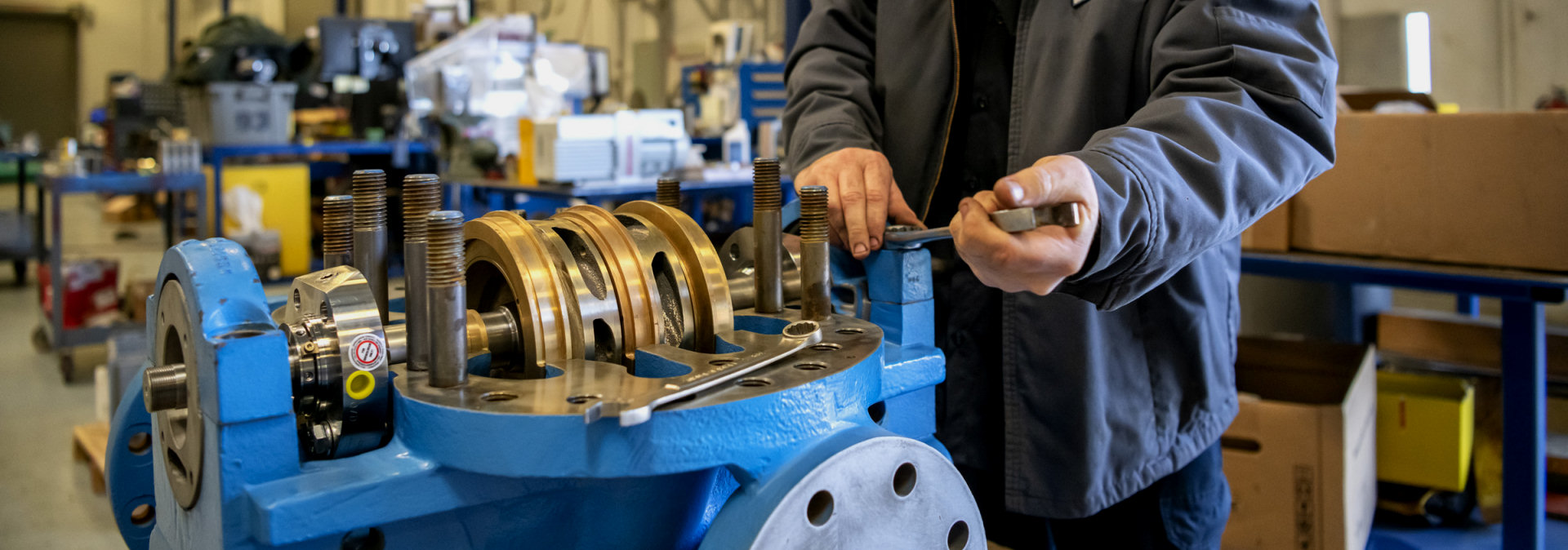
Pump Repair
Ensure fluid process equipment is fixed right the first time. Our factory-authorized certifications coupled with factory-trained service technicians, ensures you're getting the best quality pump rebuild.
See Details
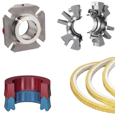
Seal Repair
Expert OEM Chesterton mechanical seal repairs conveniently located at Phoenix Pumps.
See Details
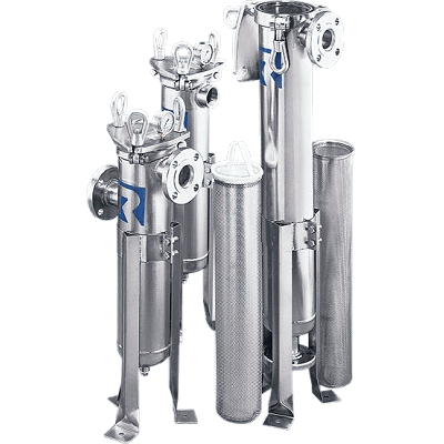
Reengineering
Re-engineering of obsolete pump parts for critical lead time repairs, improved efficiency & extended life.
See Details
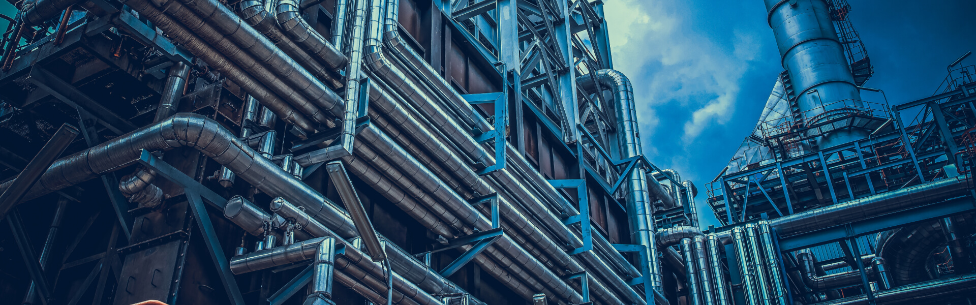
Installation & Start-Up
Proper fluid process equipment installation and start-up is vital to the long term operation. Get started on the right foot with professional installation and start-up.
See Details
Preventive Maintenance
Go From Reactive to Proactive with a Maintenance Plan from Phoenix Pumps. With a predictive or preventive maintenance plan, we'll help you minimize unscheduled repairs and plan for necessary repairs in the future.
See Details
Asset Management
Quickly access your pump asset information including specifications, manuals, videos and more.
See Details
Reliability Solutions
Customized equipment reliability solutions to maximize your plant's productivity.
See Details